Industrial Gas Power Distribution: Proven Reliable Solution
Industrial Gas Power Distribution: Proven Reliable Solution
From Temporary Power to Intelligent Permanent Distribution
Industrial Gas Power Distribution is a critical part of maintaining safe and continuous production in an industrial gas facility. Unlike ordinary commercial power distribution projects, an industrial gas production site places higher demands on electrical reliability, equipment coordination, monitoring capability, and operational control.
In this project, the electrical system was required to support the plant through different stages of development. Power was needed not only after the production facility entered formal operation, but also during the earlier construction and equipment installation stages. This meant that the overall electrical solution had to consider temporary power supply, containerized substation requirements, permanent medium-voltage distribution, low-voltage distribution, final distribution, intelligent monitoring, and long-term maintenance as one connected system.
The main electrical equipment configuration included KYN28-12 high-voltage switchgear, MNS low-voltage switchgear, and conventional distribution boxes. These devices formed the core of the project’s medium- and low-voltage distribution architecture. The system was designed to distribute electrical power safely from the upstream supply network to different production equipment, auxiliary systems, control equipment, and other electrical loads throughout the facility.
However, this project was not simply a conventional switchgear supply project.
The customer placed particularly high requirements on the manufacturing and assembly quality of the electrical equipment. The internal arrangement of components, secondary wiring, control circuits, monitoring devices, and communication-related interfaces required careful coordination during both electrical design and panel assembly.
Major high- and low-voltage electrical components were also required to use specified ABB series products. This requirement increased the importance of accurate component selection, correct installation, system compatibility, and overall manufacturing consistency. The purpose was not simply to use branded components, but to ensure that the complete Industrial Gas Power Distribution system met the electrical design requirements of the project.
Another important requirement was intelligent electrical monitoring.
The power distribution system needed to do more than distribute electricity. It also had to provide operating information that could help technical personnel understand the status of the electrical system. Power-related parameters and electrical operating data needed to be measured and monitored so that the operation of the power distribution network could be observed more effectively.
In addition, the project required a complete electrical fire monitoring system.
Electrical fire monitoring added another layer of supervision to the power distribution system. Instead of relying only on conventional switchgear protection functions, the monitoring system provided additional information related to electrical safety and abnormal operating conditions. This was especially important for an industrial production environment where stable operation and electrical safety had to be considered throughout the production process.
Remote operation was also included in the project requirements.
This meant that the Industrial Gas Power Distribution system could not be designed only around local switchgear operation. Electrical equipment, measurement devices, monitoring functions, and control interfaces had to be considered as part of an integrated system. Through the monitoring and control architecture, authorized operators could obtain relevant system information and perform required remote operations according to the final control design.
The project therefore required close coordination between conventional electrical distribution technology and intelligent monitoring technology.
The medium-voltage system, low-voltage switchgear, distribution boxes, ABB electrical components, electrical fire monitoring devices, power monitoring functions, and remote operation requirements could not be treated as independent products. They had to work together as one complete electrical system.
The project scope extended even further.
During the early construction stage, the production facility had not yet entered permanent operation, but construction, installation, and commissioning activities already required electricity. Temporary power therefore became an important part of the project planning.
Containerized substation requirements also had to be considered as part of the temporary and supporting power infrastructure.
After the construction stage, the electrical system needed to transition toward the permanent Industrial Gas Power Distribution network. The final system would then support the continuous operation of the industrial gas production facility.
Because the project covered several different stages, responsibility extended from early electrical design to equipment manufacturing and later on-site implementation.
The electrical project included:
-
Early-stage electrical system planning and design
-
Temporary power supply requirements
-
Containerized substation requirements
-
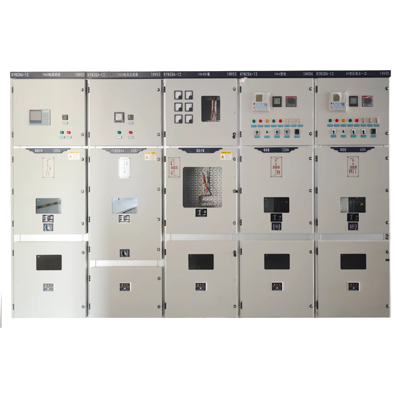
KYN28-12 high-voltage switchgear
-
MNS low-voltage switchgear
-
Conventional distribution boxes
-
Specified ABB electrical components
-
Electrical fire monitoring
-
Electrical parameter and power monitoring
-
Remote monitoring and operation
-
Electrical installation
-
System commissioning
-
Later operation and maintenance support
This full-process approach allowed the different stages of the electrical project to remain connected rather than being divided among unrelated systems.
From the construction period to formal production, the objective remained consistent: the electrical system had to provide a stable and safe power foundation for the industrial gas production process.
For this reason, the value of the project was not limited to the manufacture of several types of switchgear. Its greater significance was the integration of temporary power, permanent power distribution, monitoring, remote control, installation, commissioning, and maintenance into a complete Industrial Gas Power Distribution solution.
The project demonstrates how a modern industrial electrical system can move beyond traditional power distribution.
It combines power supply, distribution, protection, measurement, monitoring, and operational control within the same engineering framework. For industrial gas production facilities, this type of integrated electrical system helps create a more controllable and reliable electrical environment for continuous plant operation.
Industrial Gas Power Distribution Requirements
The requirements for Industrial Gas Power Distribution are more demanding than those of a basic commercial or general-purpose electrical project. An industrial gas facility typically contains production equipment, auxiliary systems, control equipment, and multiple electrical loads that depend on a stable and coordinated power supply.
For this project, the electrical system had to accommodate both construction-stage power requirements and the permanent power network. The design therefore had to account for temporary electricity, containerized substation requirements, medium-voltage distribution, low-voltage distribution, electrical monitoring, fire monitoring, and remote operation within one coordinated framework.
Power Requirements During the Construction Stage
Before the permanent electrical system is fully commissioned, construction and installation activities already require power.
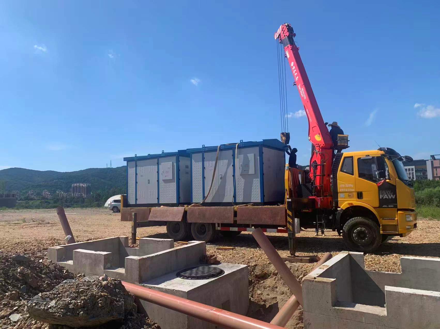
Electrical tools, mechanical equipment, temporary facilities, lighting, testing equipment, and commissioning activities all depend on a suitable temporary supply. The temporary system therefore cannot be treated as an afterthought. It needs to be considered alongside the permanent distribution architecture.
For this project, temporary power was included in the overall electrical scope, together with a containerized substation requirement. This allowed the project to address the practical power needs of the construction stage before the permanent distribution system was placed into normal service.
A properly planned temporary system also helps separate construction loads from the future production distribution network. This makes the transition to permanent power more structured and reduces the need for improvised temporary connections during installation and commissioning.
The key consideration was not simply to provide electricity at the construction site. The temporary arrangement needed to fit into the overall electrical engineering plan.
Permanent Power Requirements for Gas Production
Once the industrial gas facility enters formal operation, the electrical system must provide stable power to production and supporting equipment.
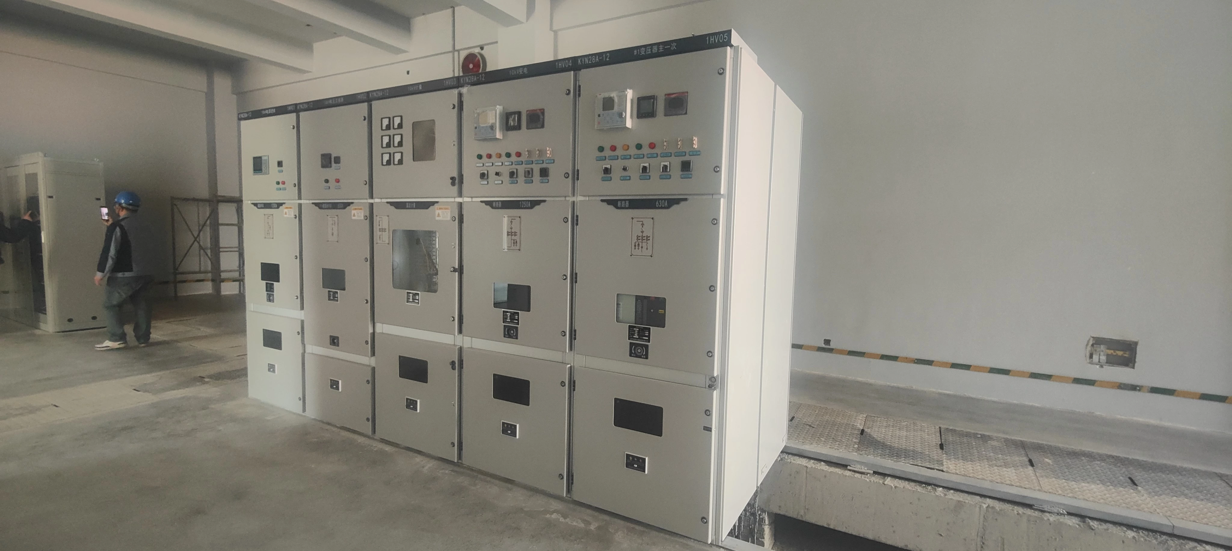
The project used 10 kV on the high-voltage side and 380 V on the low-voltage side. The transformation system included two transformers rated at 2,000 kVA and 1,600 kVA.
The medium-voltage distribution system consisted of 15 high-voltage switchgear units, while the low-voltage distribution system consisted of 18 low-voltage switchgear units.
This configuration required clear coordination between the incoming medium-voltage system, transformers, low-voltage switchgear, and downstream distribution circuits.
The basic power path can be represented as:
10 kV High-Voltage Distribution → Transformers → 380 V Low-Voltage Distribution → Downstream Loads
At the medium-voltage level, the high-voltage switchgear provides the distribution and protection interface between the incoming supply and the transformer system. The transformers then convert the voltage for the low-voltage network. On the low-voltage side, MNS switchgear distributes power to downstream circuits and equipment.
This structure provides the physical foundation of the Industrial Gas Power Distribution system.
However, power delivery alone was not sufficient for this project.
The customer also required the electrical network to be observable and controllable during operation.
From Power Distribution to Power Visibility
A modern industrial electrical system needs to provide more than a physical path for electricity. Operators also need access to relevant information about system conditions.
For this project, the monitoring system was required to measure and monitor electrical parameters and power-related information. This provided technical personnel with greater visibility into the operating condition of the distribution network.
The requirement became more significant because the system contained multiple high-voltage and low-voltage switchgear units, transformers, distribution circuits, and production loads.
Without centralized monitoring, operators would have to rely more heavily on local inspection. With monitoring functions, relevant operating information can be collected and communicated through the electrical monitoring architecture.
The project used RS485 communication as part of this monitoring system.
The resulting structure can be viewed in three layers:
Power Distribution → Electrical Monitoring → Operational Control
The first layer delivers electrical power.
The second collects and communicates operating information.
The third supports the project's requirement for remote operation.
This approach turns the distribution system from a purely physical infrastructure into a more observable electrical platform.
Electrical Safety as a Core Requirement
Electrical safety was another important part of the project requirements.
In addition to conventional electrical protection and monitoring functions, the project required a complete electrical fire monitoring system. This added a dedicated safety-monitoring layer to the power distribution system.
The purpose of this system was to provide additional monitoring of electrical conditions and support the identification of abnormal situations that could create electrical safety concerns.
Electrical fire monitoring should not be viewed as a replacement for conventional protection devices. Instead, the two functions complement each other.
Protection equipment is responsible for the designed electrical protection functions.
Measurement equipment provides operating data.
Electrical monitoring provides visibility into system conditions.
Electrical fire monitoring provides an additional layer of safety supervision.
Coordinating these functions is particularly important in an industrial production environment, where electrical equipment supports continuous processes and multiple loads may operate simultaneously.
Coordinating Power, Monitoring, and Control
The requirements of this project ultimately created three closely connected engineering priorities.
The first was stable power distribution.
The 10 kV medium-voltage network, transformers, 380 V low-voltage network, switchgear, and distribution boxes needed to form a coordinated power supply structure.
The second was electrical visibility.
Power and electrical parameters needed to be measured and communicated so that technical personnel could understand relevant operating conditions.
The third was operational control.
The monitoring and control architecture needed to support remote operation according to the project's requirements.
These functions could not be designed independently.
For example, monitoring equipment needs to be compatible with the electrical equipment and communication architecture. Control functions also need to correspond with the equipment configuration and electrical design. Component selection, cabinet assembly, secondary wiring, and communication interfaces therefore become important parts of the overall engineering process.
This is why the project's requirements went beyond selecting standard switchgear models.
The electrical system had to combine distribution, protection, measurement, monitoring, fire safety, communication, and control into a coordinated solution.
The combination of 10 kV distribution, 380 V distribution, 2,000 kVA and 1,600 kVA transformers, 15 high-voltage switchgear units, 18 low-voltage switchgear units, RS485 communication, electrical monitoring, and remote operation established a relatively complex electrical environment.
The next challenge was how to manufacture and assemble this equipment to the required standard.
The customer placed particularly high expectations on assembly quality, electrical technology, specified ABB components, and system integration. These requirements became a key consideration in the detailed design and manufacturing stage.
Main Challenges of the Industrial Gas Power Distribution Project
The Industrial Gas Power Distribution project presented several technical challenges that went beyond the supply of standard switchgear. The difficulty was mainly related to manufacturing precision, assembly quality, electrical monitoring, component integration, and coordination between multiple system functions.
The project required high-voltage and low-voltage equipment to operate as part of one electrical system. At the same time, the switchgear had to accommodate specified ABB series components, monitoring devices, communication interfaces, and control functions.
This combination increased the requirements for detailed engineering and factory assembly.
High Switchgear Assembly Requirements
One of the most important challenges was the high standard required for switchgear assembly.
For this project, the electrical cabinets were not treated as simple enclosures for installing components. The internal arrangement had to support the electrical design, protection functions, measurement requirements, monitoring system, and future operation.
The KYN28-12 high-voltage switchgear and MNS low-voltage switchgear had different electrical functions and internal configurations. Each cabinet required a clear arrangement of primary equipment, secondary components, control wiring, terminals, and auxiliary devices according to the approved design.
Poor internal organization could create practical problems during commissioning and maintenance.
For example, unclear wiring routes can make inspection more difficult. Incorrect terminal identification can increase commissioning time. Inadequate separation between different circuits can also affect the quality and maintainability of the finished cabinet.
For an industrial gas facility, these details matter because the switchgear becomes part of a larger operating system.
-
Measurable Assembly Quality Controls
High assembly quality needs to be controlled through measurable inspection points rather than subjective visual judgment alone.
For this project, quality control can be organized around several verifiable items.
First, component quantity and model verification.
The actual components installed in each cabinet should be checked against the approved bill of materials and electrical drawings. The inspection record should confirm the component model, rated parameters, quantity, and installation position.
This is particularly important where ABB series components are specified.
A simple component verification record can include:
| Quality Control Item | Verification Method | Record |
|---|---|---|
| Component model | Compare with approved BOM and drawing | Pass / Fail |
| Component quantity | Physical count | Actual quantity |
| Component position | Compare with layout drawing | Pass / Fail |
| Terminal identification | Check against wiring diagram | Pass / Fail |
| Device labels | Visual and drawing comparison | Pass / Fail |
| Auxiliary components | BOM and physical inspection | Pass / Fail |
This approach creates a traceable connection between the electrical design and the finished cabinet.
Second, terminal and wiring verification.
Every control and monitoring circuit should have a clear terminal identification. Wiring numbers should correspond with the approved schematic.
The inspection should verify wire numbering, terminal numbering, connection points, and routing.
For critical control circuits, point-to-point continuity testing can also be recorded. This helps identify open circuits, incorrect connections, or wiring mistakes before the equipment reaches site commissioning.
Third, mechanical fastening inspection.
Components, terminals, busbar-related assemblies, and other mechanical connections need to be securely installed.
Where the approved manufacturing procedure specifies tightening torque values, calibrated torque tools can be used and the results recorded.
The important principle is simple:
Specified torque → Controlled tool → Recorded result
The actual torque values should come from the approved component manufacturer's requirements or project documentation. They should not be replaced by generic values.
Fourth, insulation and electrical testing.
After assembly, appropriate electrical tests can be performed according to the approved inspection and test plan.
Depending on the equipment and applicable requirements, this may include insulation resistance testing, dielectric testing, protective circuit verification, functional testing, and other required routine tests.
The test results should be recorded by cabinet or test item.
This provides measurable evidence that the completed equipment has passed the required factory inspection.
Fifth, functional verification.
Switching mechanisms, indication circuits, protection-related functions, measurement devices, auxiliary contacts, and control interfaces should be checked against the approved design.
The objective is not simply to confirm that a component is installed.
The objective is to confirm that the component performs the intended function.
These controls are especially important in Industrial Gas Power Distribution, where cabinet quality directly affects later commissioning, troubleshooting, and maintenance.
-
Primary and Secondary Circuit Coordination
A major assembly challenge was coordinating the primary electrical circuit with the secondary control and monitoring circuits.
The primary circuit carries the main electrical power. It includes the switching and distribution equipment that forms the physical power path.
The secondary circuit supports functions such as measurement, indication, control, protection, communication, and monitoring.
These two parts cannot be designed as completely separate systems.
The position of a primary component can affect the routing of secondary wiring. The installation position of a monitoring device can affect terminal access. The arrangement of control components can affect cabinet maintenance and commissioning.
For this reason, detailed assembly required more than following a component list.
The manufacturing team needed to understand how the electrical system was intended to operate and then translate that design into a physical cabinet.
This was particularly important for the Industrial Gas Power Distribution project because the equipment had to support both conventional electrical functions and intelligent monitoring requirements.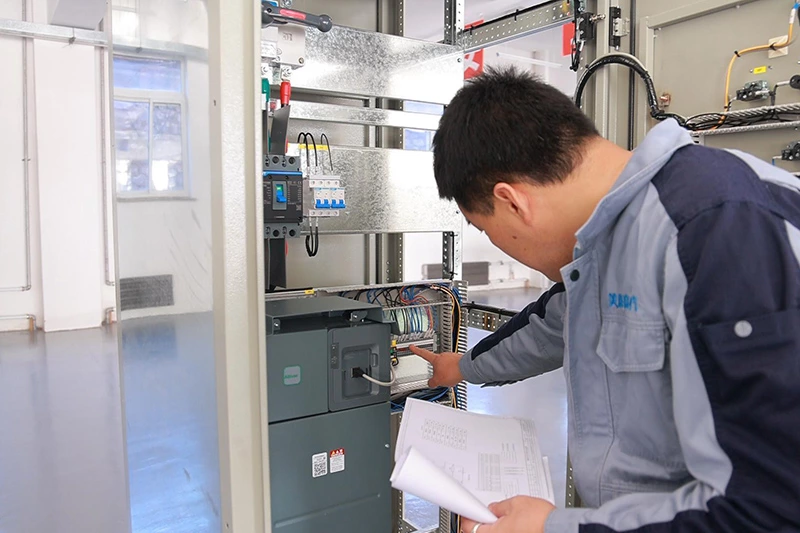
Complex Electrical Monitoring Requirements
The second major challenge was the complexity of the electrical monitoring requirements.
The project required monitoring of electrical parameters and power-related information. It also required a complete electrical fire monitoring system and remote operation functions.
These requirements added a significant amount of secondary-system work to the traditional power distribution architecture.
A conventional switchgear system can be designed primarily around power distribution and electrical protection.
This project required additional consideration for measurement, communication, monitoring, fire safety supervision, and remote operation.
Each function needs reliable signal acquisition and appropriate interfaces.
-
Multiple Monitoring Signals
The monitoring system needed to collect information from different parts of the distribution network.
The project included 15 high-voltage switchgear units and 18 low-voltage switchgear units, together with transformers and downstream distribution equipment. This created multiple potential measurement and monitoring points.
The engineering challenge was therefore not simply installing individual meters or monitoring devices.
The monitoring points had to correspond with the electrical equipment.
The collected information also needed to be organized in a way that could support system-level observation.
This requires accurate identification of signals and clear relationships between equipment and monitoring points.
If a signal is incorrectly connected or incorrectly identified, the problem may not be immediately visible from the physical cabinet. It may only appear during commissioning or system operation.
Therefore, secondary wiring quality became an important part of the monitoring system's reliability.
-
RS485 Communication Integration
The project used RS485 communication for the monitoring system.
This introduced another layer of engineering requirements.
Communication wiring had to be correctly connected to the relevant monitoring devices. Device addresses and communication relationships also needed to correspond with the monitoring architecture.
The communication network therefore had to be considered during cabinet assembly rather than added after the electrical equipment had already been completed.
A measurable quality-control approach can be applied here as well.
The factory inspection can verify each communication device against the communication schedule. Device addresses can be checked against the approved configuration. Communication terminals can be checked point by point. Where applicable, communication tests can confirm whether the required devices can exchange data correctly.
The resulting records should identify the tested cabinet, device, communication interface, and test result.
This is more useful than simply stating that “RS485 communication was installed.”
It provides evidence that the communication layer has been checked.
-
Coordination Between Measurement and Control
The project also required remote operation.
This meant that monitoring could not be considered only as a data collection function.
The system needed to support a relationship between measured information and operational control.
Operators need to know the condition of electrical equipment before performing relevant control actions. The monitoring system therefore becomes an important interface between the physical switchgear and the operating personnel.
This creates a practical engineering requirement.
Measurement signals, status signals, control signals, communication interfaces, and switching equipment must correspond correctly.
The cabinet assembly must therefore support the complete signal chain:
Electrical Equipment → Measurement and Status Signals → Communication → Monitoring System → Operational Control
Each link can be included in the commissioning checklist.
For example, the inspection can verify whether the expected equipment status is correctly reflected by the monitoring interface. It can also verify whether the intended control command produces the corresponding equipment response, subject to the approved operating logic and safety procedures.
This creates a measurable connection between physical equipment and digital monitoring.
-
Electrical Fire Monitoring Integration
The electrical fire monitoring requirement created another layer of complexity.
The project required a complete electrical fire monitoring system in addition to conventional electrical protection and power monitoring.
These systems perform different functions, so they must be coordinated without confusing their roles.
The conventional protection system focuses on protecting electrical equipment and circuits according to the electrical design.
The power monitoring system focuses on operating parameters and electrical information.
The electrical fire monitoring system provides additional supervision related to electrical safety.
The challenge was to integrate these functions into the project without creating unnecessary interference between different systems.
This required careful consideration of device installation, signal wiring, cabinet space, terminal arrangements, communication interfaces, and system commissioning.
The quality-control process can therefore include device identification, wiring verification, alarm-signal verification, communication checks, and functional testing according to the approved system design.
The final inspection record should clearly distinguish between power protection, electrical measurement, power monitoring, and electrical fire monitoring.
Why These Challenges Matter
The main difficulty of this project was therefore the interaction between multiple requirements.
High assembly standards affected cabinet manufacturing.
Specified ABB components affected component selection and physical layout.
Electrical monitoring affected secondary wiring and communication interfaces.
Remote operation affected control and signal design.
Electrical fire monitoring added another safety-monitoring layer.
These requirements were interconnected.
A problem in one area could affect another. An incorrectly installed component could influence wiring. An incorrect signal connection could affect monitoring. A communication problem could reduce remote visibility. Poor cabinet organization could make commissioning and maintenance more difficult.
For this reason, the project required an engineering approach that considered the switchgear as a complete system rather than a collection of individual components.
The core challenge of Industrial Gas Power Distribution was not simply making the equipment work electrically. It was ensuring that power distribution, component selection, assembly, measurement, communication, monitoring, and control could operate together in a consistent and maintainable configuration.
A strong quality-control process therefore needs measurable checkpoints at each critical stage. Component verification, wiring inspection, terminal identification, fastening control, electrical testing, communication testing, and functional verification can provide objective evidence before shipment.
The next stage is to examine how the MNS low-voltage switchgear and KYN28-12 high-voltage switchgear were configured to meet these technical requirements while maintaining a clear and reliable electrical architecture.
MNS and KYN28-12 Switchgear Configuration
The switchgear configuration determines how electrical power moves from the incoming supply to the final loads. In this industrial gas power distribution project, the configuration combines KYN28-12 high-voltage switchgear, MNS low-voltage switchgear, and conventional distribution boxes. Each equipment level has a defined electrical role.
The project uses a 10 kV high-voltage system and a 380 V low-voltage system. Two transformers are rated at 2,000 kVA and 1,600 kVA. The high-voltage side includes 15 switchgear units. The low-voltage side includes 18 switchgear units.
This arrangement creates a clear distribution hierarchy. It also provides a practical interface between high-voltage power supply, transformer distribution, low-voltage power management, and terminal loads.
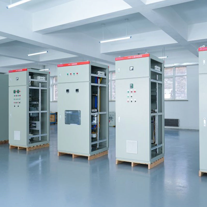
MNS Low Voltage Switchgear
The MNS low-voltage switchgear forms the main distribution level on the 380 V side. Its primary function is to receive transformed electrical power and distribute it through multiple outgoing circuits.
For an industrial gas facility, the low-voltage distribution system normally serves different types of electrical loads. These can include production equipment, auxiliary systems, pumps, ventilation equipment, control equipment, lighting, and other plant services. The exact load arrangement depends on the approved electrical design.
The use of multiple outgoing circuits allows different loads to be separated at the distribution level. This is important for both operation and maintenance. Instead of treating the entire low-voltage system as one electrical circuit, individual feeders can be arranged according to the project distribution requirements.
This structure also improves fault isolation. When a particular outgoing circuit requires inspection or experiences an electrical fault, the corresponding feeder can be isolated according to the approved operating procedure. Other circuits may remain in service when the system design and operating conditions allow it.
Electrical integration is another important function of the MNS system. The switchgear is not only a collection of circuit breakers and busbars. It provides an organized platform for power distribution, protection, measurement, control, and communication.
In this project, monitoring requirements are integrated into the electrical distribution structure. Electrical parameters and power consumption need to be monitored. The monitoring system uses RS485 communication to exchange information with connected devices.
This means that the physical switchgear arrangement must support the requirements of the electrical monitoring system. Device installation, wiring, terminal identification, communication connections, and auxiliary circuits all need to correspond with the approved drawings and control architecture.
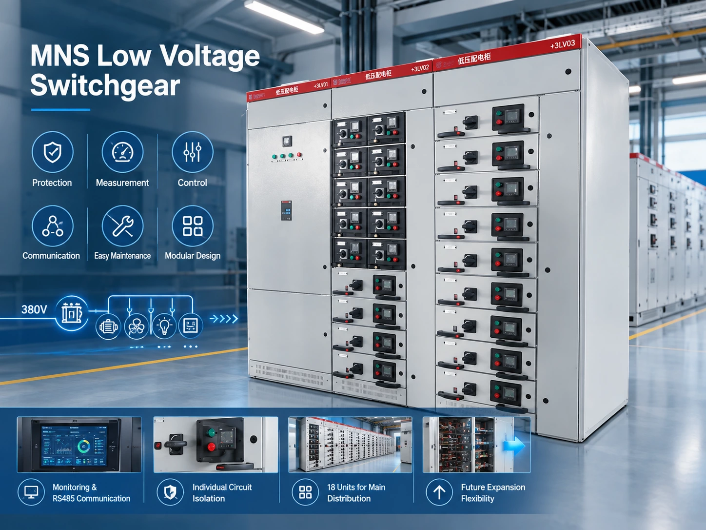
The project therefore treats the switchgear as part of a complete electrical architecture rather than as an isolated product.
Expansion flexibility is another consideration. Industrial facilities can change over time. New production equipment may be added. Existing equipment may be replaced. Auxiliary systems may also require additional power.
A modular low-voltage switchgear structure can provide a more practical foundation for future modification. The available space, busbar capacity, feeder arrangement, protection coordination, and spare capacity must still be determined by the project design. Expansion should never be assumed simply because a switchgear system is modular.
The 18 low-voltage switchgear units in this project provide the main low-voltage distribution platform. Together with the downstream distribution boxes, they establish a structured transition from central power distribution to individual electrical loads.
KYN28-12 High Voltage Switchgear
KYN28-12 high-voltage switchgear is used on the high-voltage side of the project. It forms an important part of the 10 kV distribution structure and provides the interface between the incoming high-voltage power system and the transformer distribution arrangement.
The correct equipment hierarchy is therefore:
10 kV High Voltage Supply → KYN28-12 High Voltage Switchgear → Transformer / Distribution → MNS Low Voltage Switchgear → Conventional Distribution Boxes → Loads
This sequence makes the power flow easier to understand.
The KYN28-12 high-voltage switchgear belongs to the primary high-voltage distribution level. Its role is different from that of the MNS low-voltage switchgear. KYN28-12 manages the high-voltage side of the electrical system, while MNS manages the main 380 V low-voltage distribution level after transformation.
The project includes 15 high-voltage switchgear units. Their arrangement is coordinated with the two transformers rated at 2,000 kVA and 1,600 kVA. The final feeder configuration, protection arrangement, and interconnection details are determined by the approved project electrical drawings.
This separation between high-voltage and low-voltage equipment is important for system organization. It allows the electrical system to be divided into clearly defined functional sections.
The high-voltage section manages the 10 kV side. The transformer provides the voltage transformation interface. The MNS system then manages the 380 V distribution network. Conventional distribution boxes provide a further downstream distribution point.
The KYN28-12 configuration also needs to coordinate with the project's monitoring and control requirements. High-voltage equipment is part of the monitored electrical system. Therefore, primary equipment, secondary circuits, measurement functions, protection functions, communication interfaces, and control wiring need to be considered together.
This is particularly important when remote operation is required. Remote operation cannot be treated simply as a software function. The electrical equipment, auxiliary circuits, control interfaces, monitoring devices, communication network, and control logic must work as an integrated system.
For this project, RS485 communication provides the communication interface specified for monitoring. The communication arrangement must therefore be consistent with the selected monitoring devices and the approved system architecture.
Another important consideration is the relationship between high-voltage distribution and transformer operation. The KYN28-12 switchgear is positioned before the transformation stage. The transformer then supplies the low-voltage distribution system.
This creates a clear boundary between the 10 kV and 380 V systems. It also makes the electrical system easier to understand during commissioning, operation, troubleshooting, and maintenance.
The configuration is therefore based on functional separation rather than simply equipment quantity. The 15 KYN28-12 high-voltage switchgear units and 18 MNS low-voltage switchgear units form connected but distinct levels of the distribution network.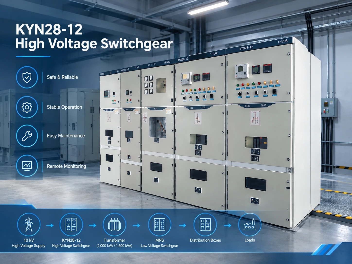
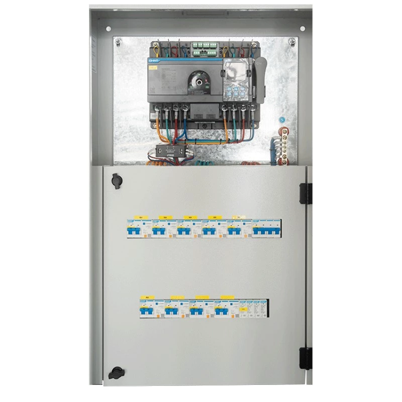
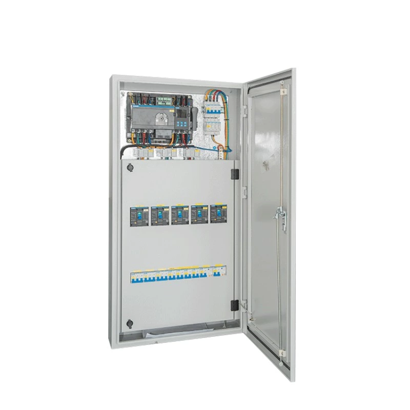
Conventional Distribution Boxes
Conventional distribution boxes provide the downstream connection between the main distribution system and individual loads.
They are positioned after the main low-voltage switchgear level. This gives the project a complete electrical hierarchy:
High Voltage Supply → KYN28-12 High Voltage Switchgear → Transformer → MNS Low Voltage Switchgear → Distribution Boxes → Loads
This hierarchy is important because the main distribution system and terminal distribution system have different functions.
The KYN28-12 high-voltage switchgear handles the high-voltage distribution level. The transformer provides voltage transformation. The MNS switchgear manages centralized low-voltage distribution. The distribution boxes then provide local or terminal-level power distribution.
Such a structure helps separate major electrical equipment from individual load circuits. It also creates clearer boundaries for operation and maintenance.
At the terminal level, distribution boxes can serve specific equipment groups or local electrical areas according to the approved design. This allows the final circuits to be organized closer to their loads.
The result is a layered distribution architecture rather than a single centralized system.
This distinction also matters when troubleshooting. If a load does not receive power, electrical personnel can trace the system through different levels. They can check the relevant distribution box, its upstream MNS feeder, the transformer supply, and finally the high-voltage distribution side.
The same principle applies to maintenance. A clearly layered system makes it easier to identify where isolation should occur and which equipment is affected by a maintenance activity. Actual isolation procedures must always follow the approved electrical operating rules and site safety requirements.
The distribution boxes also complete the physical connection between the main distribution network and the final loads. Without this downstream level, the main switchgear would not provide a sufficiently organized interface for every terminal circuit.
Therefore, the project configuration is not simply a combination of three equipment types. KYN28-12 high-voltage switchgear, MNS low-voltage switchgear, and conventional distribution boxes form a coordinated electrical distribution chain.
The KYN28-12 system establishes the high-voltage distribution level. The transformer establishes the voltage conversion stage. The MNS system establishes the main low-voltage distribution level. The conventional distribution boxes establish the terminal distribution level.
This hierarchy provides a clear path for electrical power, protection, monitoring, maintenance, and future system management.
It also supports the broader requirements of an industrial gas power distribution project. The system must not only deliver electrical power. It must also provide a structured framework for monitoring, control, maintenance, and safe operation.
Industrial Power Distribution Hierarchy
The value of this configuration is therefore found in its complete hierarchy. The main distribution system and the terminal distribution system are connected through defined electrical levels. Each level has a specific responsibility.
For industrial facilities with complex electrical loads, this approach provides a more understandable and maintainable distribution structure. It also creates a practical foundation for integrating electrical monitoring, remote operation, and other intelligent electrical functions without losing the basic clarity of the power distribution system.
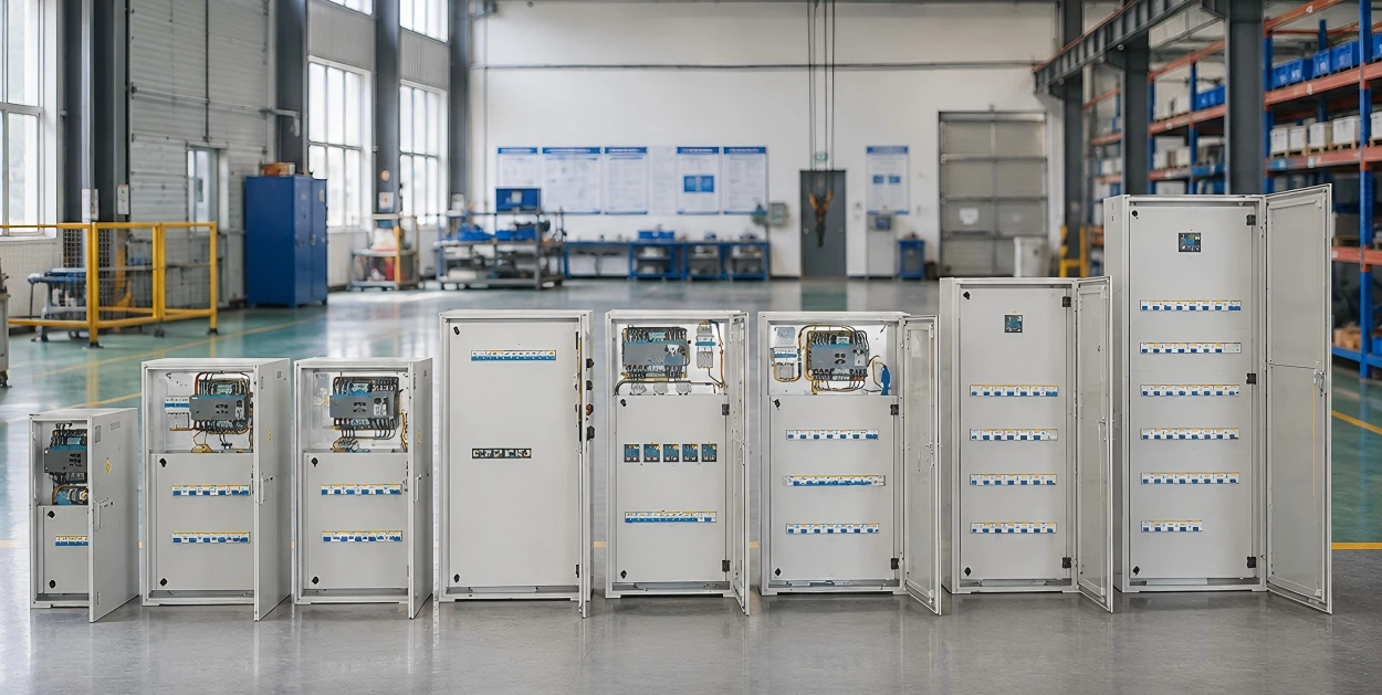
ABB Components and High-Standard Assembly
The use of ABB components in an industrial gas power distribution project is not simply a purchasing decision. It is part of the overall engineering standard.
When a project specifies a particular electrical brand, the requirement usually extends beyond the name printed on a component. The selected equipment must be suitable for the intended electrical application. Its technical parameters must correspond with the approved design. Its installation must be compatible with the switchgear structure. Its auxiliary circuits and secondary wiring must also work correctly with the wider control and monitoring system.
For this reason, ABB component requirements need to be considered from several connected perspectives. These include component selection, model verification, installation compatibility, secondary wiring, cabinet layout, technical documentation, and system coordination.
The objective is not simply to install branded components. The objective is to build an electrical distribution system in which the selected components work together as part of a defined engineering solution.
Why Component Brand Specification Matters
From an engineering procurement perspective, a specified component brand often indicates that the project has already established a certain technical standard.
The brand may be connected with the project's electrical design philosophy, protection concept, equipment compatibility, maintenance expectations, and technical documentation requirements. Once such a requirement has been established, a supplier should not treat the specified brand as an optional purchasing preference.
Unauthorized substitution can create technical uncertainty.
Even when another component appears to have similar basic electrical characteristics, its dimensions, connection arrangement, auxiliary contacts, control interface, protection characteristics, installation requirements, or communication compatibility may differ.
That is why component authenticity + correct model + correct technical application should be considered together.
ABB Electrical Components and Industrial Distribution
Component authenticity is the first consideration. Industrial electrical equipment must use genuine components that correspond to the approved procurement requirements. Authenticity supports traceability and reduces the risk of receiving products with uncertain origin or inconsistent technical characteristics.
The second consideration is model verification.
A supplier needs to verify that the selected component corresponds to the approved engineering requirement. This verification should cover the information that is relevant to the application. It should not rely only on a product name or a general category description.
The third consideration is technical application.
A genuine component can still be unsuitable if it is applied incorrectly. Electrical components must be selected and installed according to their intended function and the approved system design.
This distinction is important for engineering procurement.
The question is not only, “Is this an ABB component?”
The more important questions are:
Is it genuine? Is the correct model being supplied? Is it technically suitable for the intended application? Can it be correctly integrated into the switchgear and control system?
These questions help convert brand specification into an effective engineering control.
Component Selection and Model Verification
Component selection begins with the electrical function that the component needs to perform.
Different positions within a switchgear system can have different electrical and control requirements. The supplier therefore needs to consider the relationship between the component and the circuit in which it will operate.
Model verification should be performed against the approved technical documents.
This includes checking relevant electrical characteristics, installation requirements, auxiliary functions, interface requirements, and physical compatibility. The exact verification points depend on the component type and its position within the system.
The purpose is to prevent a common procurement problem: selecting a component that appears suitable from a general product description but does not fully match the engineering application.
The same principle applies when components are prepared for production.
The component model needs to remain consistent between procurement, engineering documentation, cabinet assembly, testing, and final documentation. A mismatch at any stage can create additional technical work later.
For example, if the component installed inside the cabinet does not correspond with the approved design documentation, the problem is not limited to procurement. It can affect wiring, cabinet layout, maintenance documentation, commissioning, and future troubleshooting.
This is why model verification should be treated as part of quality management rather than as a simple purchasing check.
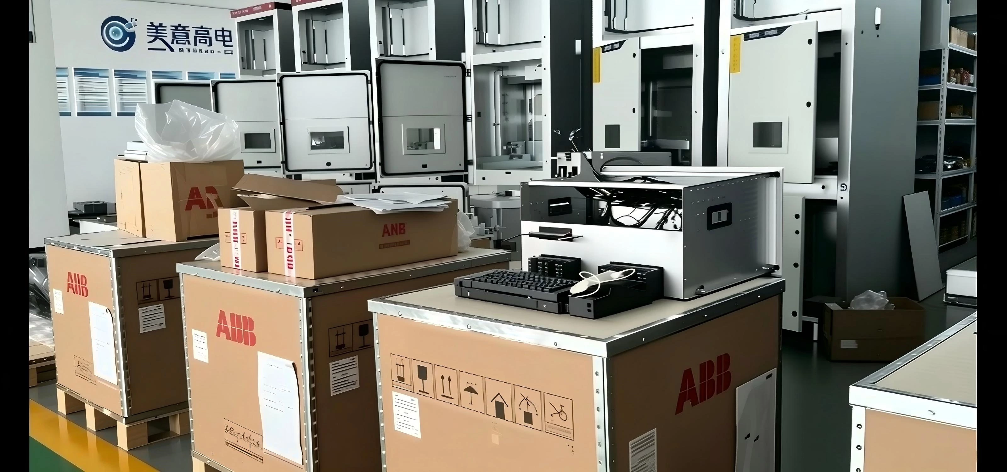
Installation Compatibility and Cabinet Layout
Brand specification also affects the physical design of the switchgear.
Electrical components occupy real space inside a cabinet. Their installation position, mounting method, cable access, terminal arrangement, heat dissipation requirements, and relationship with neighboring equipment all need to be considered.
The cabinet layout therefore needs to be developed around the actual technical requirements of the selected components.
A well-planned layout can make wiring clearer and maintenance more convenient. It can also reduce unnecessary crossing of control wires and improve the identification of functional sections.
For MNS low-voltage switchgear, this becomes especially important because the cabinet may contain multiple outgoing circuits and various electrical functions.
The arrangement must provide a practical relationship between the main electrical circuits, auxiliary circuits, measurement devices, control equipment, and communication interfaces.
The objective is not to maximize the number of components placed inside a cabinet.
The objective is to create an organized electrical assembly that can be manufactured, inspected, operated, and maintained.
Installation compatibility should therefore be verified before final assembly. The supplier needs to confirm that the selected components can be properly mounted and connected within the designed cabinet structure.
This also affects future maintenance.
A component that is technically correct but difficult to access can increase maintenance time. A poorly organized cabinet can make fault diagnosis more difficult. A clear cabinet layout, by contrast, gives electrical personnel a more understandable physical representation of the circuit design.
Secondary Wiring and System Interfaces
Secondary wiring is another critical part of ABB component integration.
The primary circuit carries electrical power. The secondary circuit supports functions such as measurement, indication, protection, control, interlocking, and communication.
These functions must be coordinated with the selected components.
In this project, electrical monitoring and remote operation are part of the overall system requirements. Therefore, the secondary wiring cannot be considered separately from the monitoring architecture.
Signal paths need to correspond with the approved electrical and control design. Terminal connections need to be identified correctly. Control interfaces need to match the equipment being controlled or monitored.
RS485 communication adds another integration requirement.
The communication system needs appropriate connections between the relevant monitoring devices and the communication network. Device addressing, communication wiring, and functional testing need to correspond with the approved system design.
The same principle applies to electrical fire monitoring.
Where electrical fire monitoring equipment is integrated into the project, the related wiring and interface requirements need to be considered during cabinet design and assembly. The monitoring system should receive the required signals and provide the intended information to the wider electrical management system.
This makes secondary wiring a system-level issue.
It is not enough for each individual wire to be connected. The complete signal chain needs to work as intended.
Technical Documentation and System Coordination
Technical documentation provides the link between engineering design and physical equipment.
For a customized electrical distribution project, documentation should allow the equipment configuration to be understood before, during, and after installation.
Relevant documents may include approved drawings, wiring diagrams, equipment specifications, component information, terminal arrangements, and inspection records, depending on the project requirements.
The exact document package should follow the contractual and technical requirements of the project.
The important principle is consistency.
The physical cabinet should correspond with the drawings. The installed components should correspond with the approved technical information. The wiring should correspond with the circuit design. The monitoring interfaces should correspond with the control architecture.
This consistency becomes particularly valuable during commissioning.
When engineers test a circuit, they need to understand what the circuit is intended to do. When an electrical technician performs maintenance, the documentation should provide a reliable reference. When the system is expanded or modified in the future, the existing documentation becomes part of the technical foundation for the new work.
System coordination therefore extends beyond the switchgear manufacturer.
The high-voltage system, transformer interface, MNS low-voltage switchgear, distribution boxes, monitoring equipment, remote control functions, and electrical fire monitoring system all need to work within the same electrical architecture.
The ABB component specification supports this architecture by establishing a defined equipment standard at the component level.
The value of this approach is consistency.
A well-integrated system should not depend on isolated component decisions. Each component should have a clear technical role. Each installation position should support the circuit function. Each secondary connection should support the required control or monitoring function. Each document should describe the actual equipment configuration.
For an industrial gas power distribution project, this level of coordination helps turn a component brand requirement into a practical engineering result.
The goal is therefore not simply to purchase ABB components.
The goal is to ensure that genuine components, correct models, compatible installation, accurate secondary wiring, organized cabinet layout, complete technical documentation, and system-level coordination form one consistent electrical solution.
Electrical Fire and Power Monitoring System
The monitoring system is integrated into the electrical distribution architecture to support power measurement, electrical parameter monitoring, and electrical fire monitoring. In this project, the confirmed communication protocol is RS485, while the specific measurement parameters are determined by the approved technical requirements.
The monitoring design therefore focuses on three practical areas: measurement points, communication interfaces, and electrical fire monitoring. These functions are coordinated with the switchgear and distribution system rather than being treated as separate equipment.
Electrical Parameter Monitoring
The project requires monitoring of electrical parameters and power measurement. The monitoring system must therefore be connected to the relevant electrical equipment and measurement points defined by the project design.
The confirmed information does not specify that every possible electrical parameter is included. Parameters such as voltage, current, frequency, power factor, active power, reactive power, and energy consumption should only be listed when confirmed by the final technical requirements.
This distinction is important when documenting an industrial electrical project. The monitoring scope should reflect the actual engineering configuration rather than a standard list of possible functions.
Industrial Electrical Parameter Monitoring System
RS485 is used as the specified monitoring communication protocol. The communication design needs to cover the relevant monitoring devices, communication wiring, device addressing, and connection to the monitoring platform.
During commissioning, the communication path can be checked from the field device through the RS485 network to the monitoring system. The objective is to confirm that the required data can be correctly transmitted and identified at the intended monitoring point.
The monitoring interfaces also need to correspond with the switchgear arrangement.
KYN28-12 high-voltage switchgear forms the 10 kV distribution level. The transformers provide the voltage transformation stage. MNS low-voltage switchgear manages the 380 V distribution level, while downstream distribution boxes serve the terminal distribution level.
The monitoring system is coordinated with these electrical levels according to the approved measurement arrangement.
This coordination affects cabinet design and secondary wiring. Monitoring devices need appropriate installation positions. Signal wiring needs correct termination. Communication connections need to follow the approved design. Equipment identification and technical documentation should remain consistent with the installed system.
The result is a monitoring structure that provides electrical operating information without adding unconfirmed functions to the project specification.
Electrical Fire Monitoring
The project also requires a complete electrical fire monitoring system.
Its basic functional relationship can be summarized as:
Distribution → Monitoring → Early Warning → Operation Management
The distribution system provides the electrical infrastructure. Monitoring devices collect the relevant information. The early-warning function identifies configured abnormal conditions. Operation management then provides the basis for inspection and response.
Electrical fire monitoring should be integrated with the overall electrical system during engineering and installation.
The relevant monitoring devices, wiring, communication interfaces, and alarm functions need to correspond with the approved system design. Functional testing should verify that the intended signals can be collected, transmitted, and presented correctly.
The system should be understood as an early-warning and monitoring function, not as an absolute guarantee against electrical fire.
Electrical safety still depends on the complete system. Equipment selection, protection, installation quality, operating procedures, inspection, maintenance, and personnel response all remain necessary.
For this project, the practical value of electrical fire monitoring is its connection with day-to-day operation. When the system identifies a configured abnormal condition, operators can receive the relevant information and follow the established response procedure.
This makes the monitoring system part of the operational workflow rather than simply another device installed inside the electrical room.
The integration also supports later maintenance. Monitoring information can help electrical personnel identify the relevant distribution area before carrying out further inspection. The actual diagnostic process must still follow site procedures and appropriate electrical safety requirements.
The overall architecture can therefore be summarized as:
10 kV High-Voltage Distribution → KYN28-12 → Transformers → 380 V MNS Distribution → Distribution Boxes → Loads
with the monitoring and electrical fire monitoring functions connected to the relevant points within this hierarchy.
This configuration keeps the electrical power path and the monitoring architecture clearly defined. It also provides a technical foundation for the project's remote operation requirements without assuming monitoring functions that have not been confirmed.
Remote Monitoring and Control
Remote operation is one of the important functional requirements of this industrial gas power distribution project.
The system is not limited to supplying electrical power through local switchgear. Electrical equipment, monitoring functions, communication interfaces, and the control platform are coordinated to support remote operation.
This changes the way operators interact with the electrical distribution system.
Instead of relying entirely on physical access to the electrical room, the project introduces a communication and control path between electrical equipment and the remote control platform.
The result is a transition from conventional electrical distribution toward intelligent industrial power distribution.
From Local Operation to Remote Operation
In a traditional distribution system, the operating process is relatively direct:
Operator → Electrical Room → Local Panel → Manual Operation
The operator needs to reach the electrical room and operate the relevant local equipment. For some routine switching and inspection activities, this physical operating mode can be practical.
However, industrial facilities can contain multiple electrical distribution points and complex operating requirements. When electrical information and control functions need to be coordinated across the system, a purely local operating model becomes less flexible.
The project therefore requires a different control architecture:
Electrical Equipment → Monitoring System → Control Platform → Remote Operation
This structure creates a communication link between the electrical equipment and the operator.
The electrical equipment provides the physical interface.
The monitoring system provides the relevant electrical information and communication functions.
The control platform provides the operating interface.
Remote operation then becomes part of the overall electrical management architecture.
[Resource Link: Intelligent Industrial Power Distribution System]
The value of this structure is particularly clear when considered from the perspective of system management.
An operator does not need to treat every electrical device as an isolated piece of equipment. The control platform can provide a centralized interface for the functions included in the approved system design.
This can make the relationship between electrical status, monitoring information, and operating commands easier to manage.
The project uses RS485 as the specified monitoring communication protocol. Therefore, communication is an important link between field-level electrical equipment and the monitoring architecture.
The communication system must be coordinated with the relevant equipment interfaces and secondary wiring. Correct physical connections alone are not sufficient. Device configuration, communication settings, signal identification, and functional commissioning also need to correspond with the approved design.
Remote operation also requires clear boundaries.
Not every electrical function should automatically be assumed to be remotely controllable. The actual remote-control scope depends on the project design, equipment functions, control logic, safety requirements, and approved operating procedures.
Therefore, this project should be described as having remote operation functions, rather than claiming that every switch or every electrical device can be controlled remotely.
This distinction keeps the technical description aligned with the actual project requirements.
The remote-control architecture also needs to work together with local operation.
A remote control platform does not eliminate the need for local electrical equipment, local indication, inspection, maintenance, and appropriate operating procedures. Instead, it adds another operating interface to the electrical system.
This creates a more flexible relationship between equipment and personnel.
For example, when the system provides relevant electrical information through the monitoring platform, the operator can first review the available status information before deciding whether further action is required. Where remote operation is permitted by the system design, an authorized operator can then perform the corresponding operation through the control platform.
The exact sequence remains subject to the project's control logic and safety procedures.
This approach is particularly relevant to industrial power distribution because electrical operation involves both power equipment and information.
The physical distribution system determines where electrical power flows.
The monitoring system provides information about the electrical system.
The control platform provides the interface for authorized operating functions.
Remote operation connects these elements into a more integrated management structure.
Intelligent Industrial Power Distribution
The combination of electrical distribution, monitoring, communication, and remote operation allows the project to move beyond a conventional equipment-only concept.
The system can be understood as four connected layers:
Power Distribution → Electrical Monitoring → Communication → Remote Operation
The power distribution layer includes the main high-voltage and low-voltage equipment.
The monitoring layer collects the required electrical information.
The communication layer transfers information between relevant field devices and the control system.
The remote operation layer provides the interface for authorized control functions.
This is the practical meaning of intelligent industrial power distribution in this project.
It does not depend on using advanced terminology for its own sake. The key point is that electrical equipment is connected with information and control functions.
KYN28-12 high-voltage switchgear remains responsible for the 10 kV distribution level. MNS low-voltage switchgear remains responsible for the main 380 V distribution level. Distribution boxes provide downstream distribution to loads.
The intelligent functions are built around this electrical foundation.
This architecture also supports the project's electrical monitoring requirements. The system needs to monitor electrical parameters and power measurement, while the electrical fire monitoring system provides a dedicated early-warning function.
These functions can provide information to the operation platform according to the approved system architecture.
The result is a more connected electrical system.
For procurement teams and project engineers, this distinction is significant. Purchasing switchgear alone does not create an intelligent distribution system. The equipment needs to support the required interfaces. Secondary wiring needs to be designed correctly. Communication needs to be established. Monitoring devices need to be integrated. Remote operation needs to correspond with the control architecture.
Therefore, intelligent industrial power distribution should be evaluated as a system integration capability, not simply as a product feature.
This also explains why electrical equipment selection and engineering design need to be coordinated from the beginning.
A switchgear cabinet may satisfy its basic power distribution function but still require additional engineering work to support monitoring and remote operation. The final solution must therefore consider electrical equipment, auxiliary circuits, communication, monitoring, control, and documentation as connected elements.
For an industrial gas facility, this integrated approach provides a clearer path from physical electrical infrastructure to digital operation.
The project starts with the basic power path.
10 kV High Voltage Supply → KYN28-12 → Transformers → 380 V MNS → Distribution Boxes → Loads
It then adds the information and control path.
Electrical Equipment → Monitoring System → RS485 Communication → Control Platform → Remote Operation
These two paths serve different purposes, but they need to operate together.
The first delivers electrical power.
The second provides information and control.
Together, they create the foundation for intelligent industrial power distribution.
[Resource Link: Remote Electrical Monitoring and Control]
The practical value is therefore not simply that an operator can operate equipment from another location. The larger value is the integration of electrical distribution with monitoring and control.
For a project requiring permanent power, temporary power, electrical monitoring, and remote operation, this architecture provides a more complete solution than a conventional local-only distribution arrangement.
It gives the electrical system a clear physical structure while adding a communication and control layer above it.
That combination makes the distribution system easier to connect with modern industrial operation and management requirements.